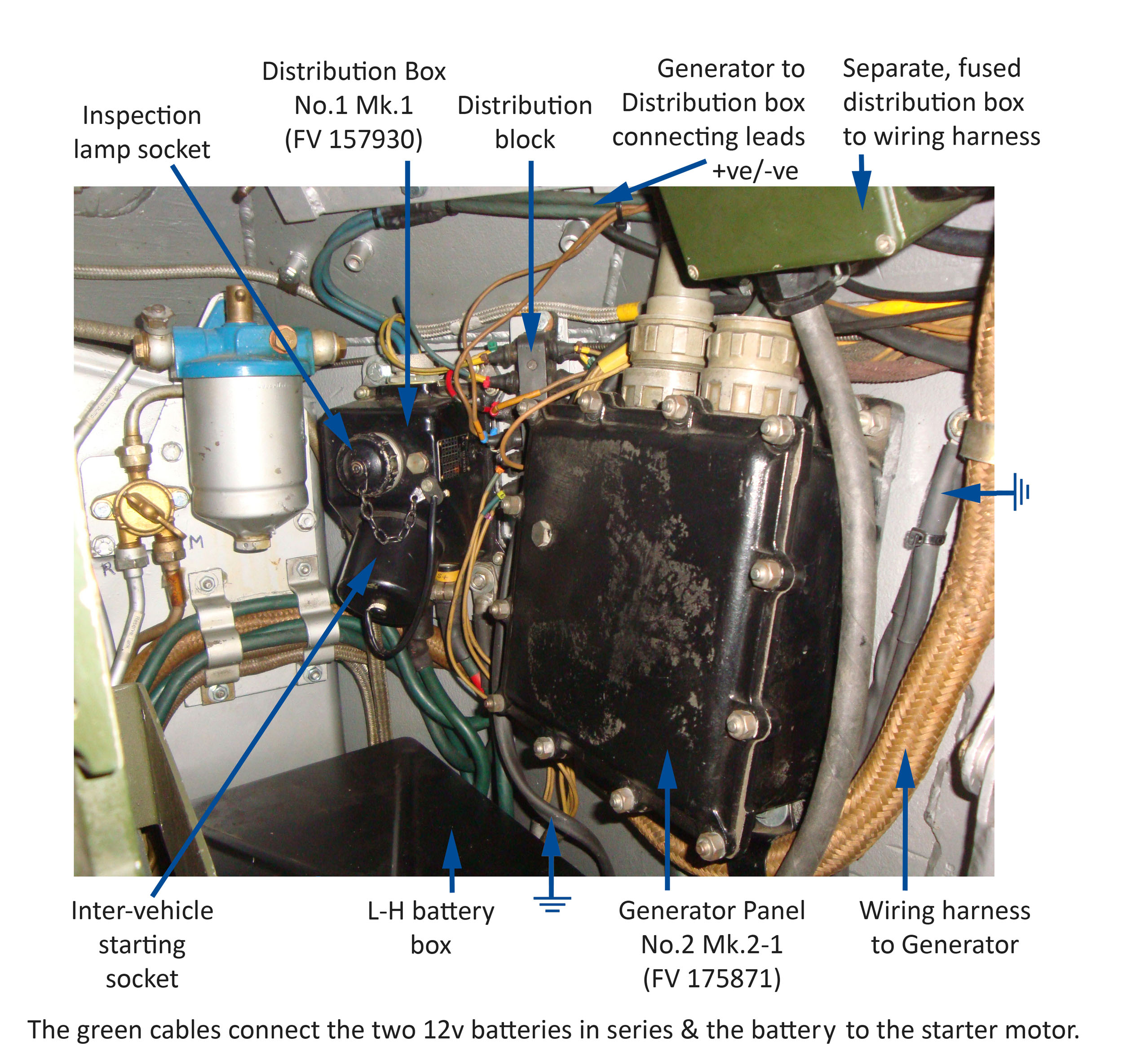
The Daimler Ferret is wired on a 24 volt negative earth wiring system. A two-speed insulated-return generator provides electrical power via a generator panel and distribution box, from which further smaller fuse-protected distribution boxes carry power to individual electrical components. I have fitted extra distribution boxes to protect the old wiring loom and electrical components. For troubleshooting the electrical system, see this page.
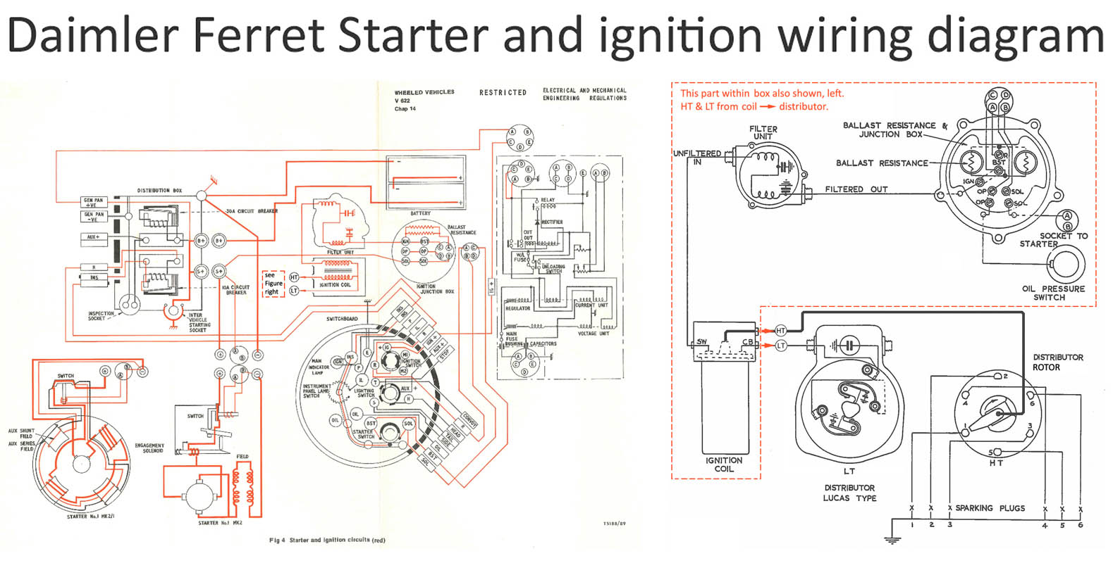
The generator panel, which controls the output of the generator (25 amps at 28 volts), is fixed on the rear left-hand wall of the fighting compartment (the wiring diagram is shown here). The maximum output of the generator is controlled by two internal carbon piles; one controls the maximum voltage to 27.8 – 29.2 volts, and the other limits the current to 25 amps. Fuses fitted in the generator panel protect the charging and indicator light circuits. The wiring diagram for the charging and indicator lamp circuits is shown here. Panel generator No. 2 Mk 2/1 is similar to Panel generator No. 2 Mk 1 and differs only in that a stabilizer coil has been added to Panel generator No. 2 Mk 2/1.
The battery and generator output leads are connected to the distribution box, from where current is distributed to the various components. The negative leads of the battery and starter motor are connected to an earthing stud fitted to the distribution box (see the wiring diagram here). The distribution box contains two thermal magnetic circuit breakers. One is a 30A unit connected in series with the exterior and interior lamps; inspection lamps sockets; horn; smoke dischargers; windscreen wiper and the radio junction box situated above the generator panel. The 30A circuit breaker connects the battery to the inspection socket on the distribution box and to a cable merging from the distribution box labelled AUX+. The wires labelled INS = Ignition-Controlled Instrument feed. The 10A circuit breaker is connected in series with the engine electrical equipment (starter solenoid; main indicator lamp; oil pressure warning lamp and switch; coolant thermometer; fuel gauge and instrument panel lamp). The wiring diagram for the lighting and auxiliary equipment circuits is shown here. The wiring diagram for the distribution box and and generator panel is shown here, and that for the instruments here. This distribution box is waterproofed; do not attempt to remove the cover.
Electrical connections to most units are made via Plessey-Breeze connector plugs and sockets, or by snap-type nipple connectors in rubber insulating blocks. Leads are housed in braided flexible metallic conduits and enter most external electrical components through tightly-fitting rubber bushes secured by gland nuts. The main wiring diagram is common to all Marks of vehicle, but an alternative relay stop light circuit is fitted to Mk1 & Mk2 vehicles. Later Marks of Ferret have a direct in-line pressure stop light switch. The 1973 wiring diagram differs from the 1969 wiring diagram of four years earlier in that it incorporates a hazard switch and an infra-red IR switch. If the brake/stop light relay fails, it may be due to corrosion inside the unit, the soldered connection, or a rivet corroding or failing. Besides this, check the electrical connections. The stop relay unit can be removed from its housing by bending (with care!) the top sealing tabs.
Any four-stroke petrol engine requires four things to work: fuel, air, compression and a spark. The Ferret ignition circuit (wiring diagram here; Driver’s Manual description here) is connected to a battery positive terminal, and thus is not affected by the thermal magnetic circuit breakers in the distribution box except upon starting the vehicle. The ignition circuit layout is shown here. The batteries are charged by the generator; the engine must not be run without the batteries being connected. The operation of the generator & charging system is described here and Ignition timing notes are here.
A 24 volt electrical system is used for two reasons. First, to achieve high starting power, since for a given electrical power requirement, the doubling of the voltage (pressure) compared with 12 volt systems, reduces the current (amps, I) by half. Without the extra 12 volts, the current load on the battery and starter circuit becomes exceptionally high, especially on a cold morning in winter. Heavy power equipment runs better off 24 volts; there is less stress on lead-acid batteries during engine starts. Higher torque starters could be made to handle higher compression engines. Also, sufficient electrical power is required for the high torque needed to overcome inertia of heavy engines. The second reason for a 24 volt system is to power the Clansman radios for long periods when the vehicle is static but with the engine idling. Another advantage of 24 volt supplies is that they are more compatible with AC appliances. For any given load, if the DC current is halved, losses are down by ¼. This also reduces any fire risk. The effect of any voltage drop is reduced because it is proportionally a smaller percentage of the initial 24 volts. Also, reducing the current means that smaller diameter wires can used. This is a good argument for fitting LED lights where possible: the current loads are very small.